1. Chain belt grate. The chain belt grate is a wide circular chain belt which is surrounded by and supported on the the front and rear axles via the chain wheels. At present, ZOZEN packaged chain grate steam boiler mainly adopts the large-block chain belt grate with a capacity of 1-20 tph.
2. Scale grate. The scale grate has many advantages. The obvious one is that there is less coal leakage. The scales can be replaced without shutting down the boiler. The ventilation is balanced, and the ventilation section is relatively small (6%). The chain grate bars only bears the stress or high temperature instead of both of them, which improves the working conditions of the chain grate.
3. Beam grate. Its main feature is that the width and length of the grate can be extended in a wide range, and the tonnage of the boiler can be larger. At present, the tonnage of the domestic beam chain grate steam boiler can reach 240 tph. The grate is featured with long service life, good durability, smooth arrangement and convenient replacement.
Chain Grate Boiler,Travelling Grate Boiler,Travelling Grate,Step Grate Boiler Jinan Yuanda Power Equipment Co.,Ltd. , https://www.ydpowerequipment.com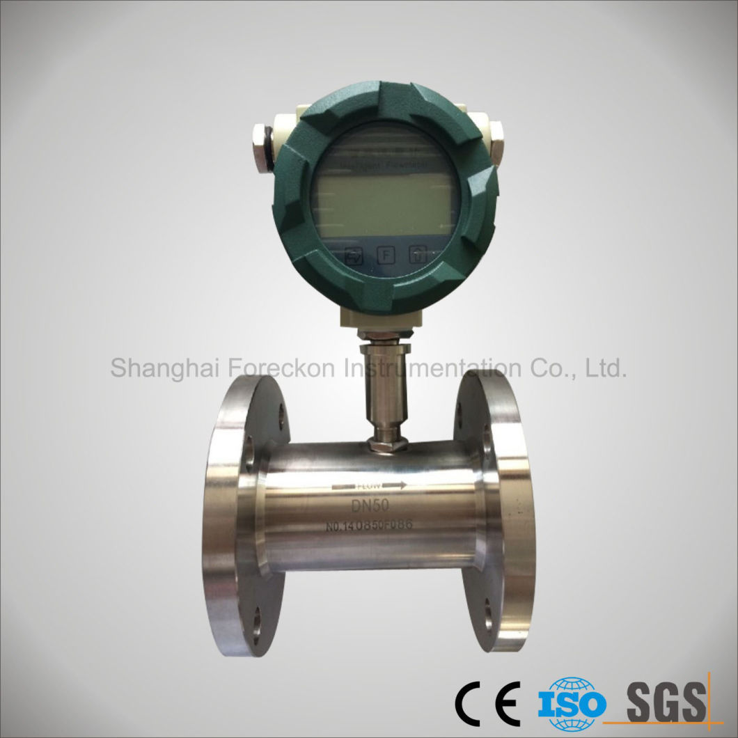
 Â
Â
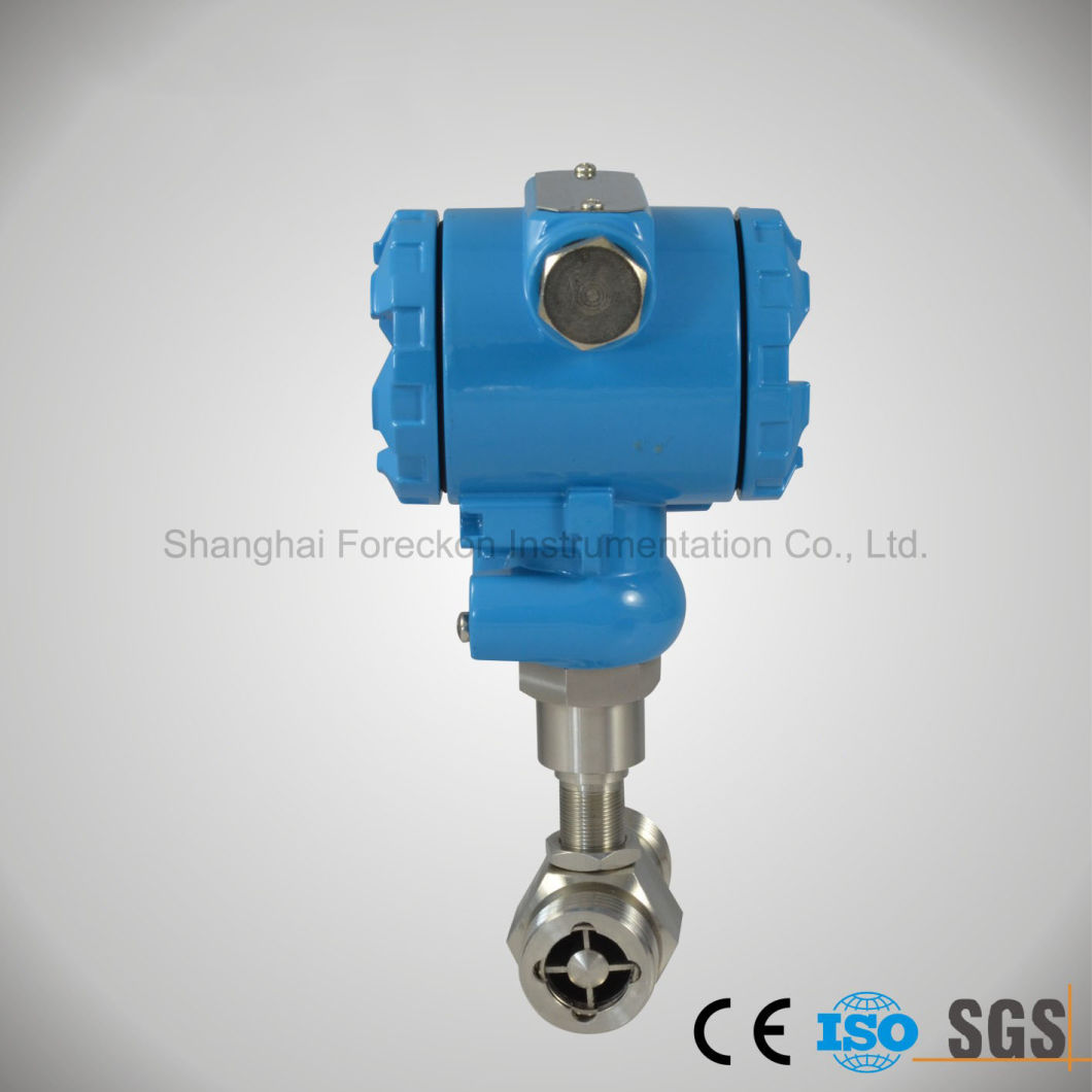
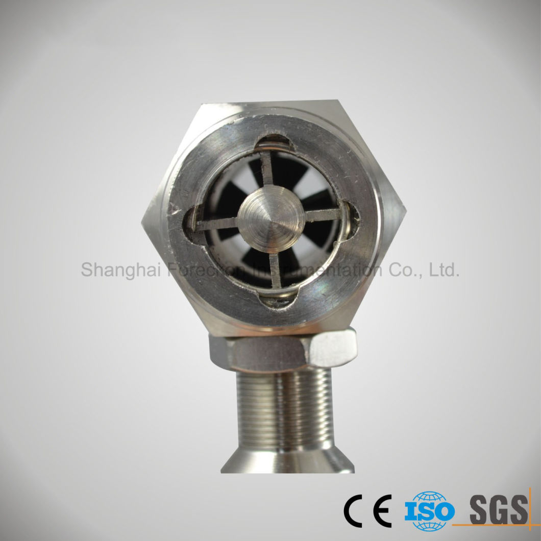
Turbine flow flowmeter adapts to measure the liquid rate and total flow rate of low viscosity, It can be widely used in the fields of Petrol,fuel ,water ,chemical industry,Metallurgy,Scientific research for measuring or control Several output and display methods can be selected.
Â
Features:
-Accuracy reaching ±1.0%F·S.
-Short-term repeatability reaching 0.05%~0.2%.
-Output pulse frequency signal, which is suitable for gross metering and connection to the computer. No zero drift and strong anti-interference capability.
-3-4kHz frequency signal , and high signal resolution.
-Wide range with 1:20 for medium and large caliber, 1:10 for small caliber.
-Compact and light structure, convenient installation and maintenance, great capability.
-Suitable for measuring high pressure. Easy to be made into high-pressure meter.
-Various kinds of specified sensors.
Â
Technical parameters:
Table 3-1
Nominal Diameter
DN(mm)
Range(m3/h)
Liquid Temperature
(ºC)
Nominal Pressure
PN(MPa)
Ambient Temp.
(ºC)
Humidity
(%)
Max. Pressure Loss
(MPa)
Error Â
0.2%*
Error   0.5%
Error     1%
Min.
Max.
Min.
Max.
Min.
Max.
2*
Â
Â
Â
Â
0.03
0.16
-20
 to
+1206.3
-25
to
+55≤ 80
0.15
4*
Â
Â
Â
Â
0.04
0.25
0.12
6
Â
Â
0.1
0.6
0.1
0.6
6.3
16
25
32*0.08
10
Â
Â
0.25
1.2
0.2
1.2
0.05
15
1.2
6
0.6
4
0.6
6
0.035
25
2
10
1.6
10
1
10
40
4
20
3
20
2
20
1.6
2.50.025
50
6
40
4
40
4
40
80
16
100
10
100
10
100
100
25
160
20
160
20
200
1.6
2.5
150
50
300
40
300
40
400
200
150
750
100
600
80
800
250*
200
1000
160
1000
120
1200
1.6
300*
Â
Â
260
1600
180
1800
Â
Table 3-2 Model and Specification Code
Model
Specification Code
Description
LW.......................................................................................
Turbine Flowmeter
Transducer
For Liquid
Â
G........................................................................
Â
Y......................
Nominal Diameter
-2*.................................................
-4*.................................................
-6..................................................
-10................................................
-15................................................
-25................................................
-40................................................
-50................................................
-80................................................
-100..............................................
-150..............................................
-200..............................................
-250..............................................
-300..............................................2mm(PT G3/8″)
4mm(PT G3/8″)
6mm(PT G3/8″)
10mm(PT G1/2″)
15mm(PT G1″)
25mm(PT G11/4″)
40mm(Flange)
50mm(Flange)
80mm(Flange)
100mm(Flange)
150mm(Flange)
200mm(Flange*)
250mm(Flange*)
300mm(Flange)
Type Code
A............................ ..........
B............................ ..........
C............................ .......Accuracy 1%
Accuracy 0.5%
Accuracy 0.2%*
Output Signal
P......................... .......
I.......................... .......
T......................... .......
M........................ .......Pulse
Analog 4 to 20mA
Total display(Battery. for 2 to 3 years)
Pulse out/4 to 20mA out and LCD display(Intelligent)
Diameter Pressure
C1................... .....
C2................... .....
C3................... .....
C4................... .....
C5................... .....
C6................... .....
C7................... .....PN1.6MPa
PN2.5MPa
PN4.0MPa
PN6.3MPa
PN16MPa(Diameter≤25mm)
PN25MPa(Diameter≤25mm)
PN40MPa*(Diameter≤25mm)
Explode Request
/NE
/EXNot Explosive
Ex ib I or Ex dIIBT4
Range of Temperature
/NT
/HTNormal Temperature(<120ºC)
High Temperature(≥120 to 150ºC)
Special Option
/
e.g.:High Temperature,Erode-resistant,Wearable etc.
Â
Â
Â
Â
Â
Â
Â
Â
Â
Â
Â
Â
             2. Mark "*" means special order.
Â
 The chain grate is the combustion equipment of coal-fired steam boiler. There are three main types and structures: chain belt grate, scale grate and beam grate.
Turbine Diesel Fuel Flow Meter (JH-LWGY)
Model NO.: JH-LWGY
Measuring Media: Liquid
Measuring Principle: Mechanics
Measurement Object: Closed Pipeline
Certification: CE, ISO
Display: LCD
Temperature: -20c~120c
Power Supply: 24VDC or Battery
Output Signal: Pulse, 4-20mA
Body Materia: Ss304/Ss316
Connection: Flange or Screw Thread
Trademark: JH
Transport Package: Carton
Specification: CE, ISO
Origin: Shanghai
HS Code: 9026100000
Liquid Turbine Flowmeter
Main Applications: