Facilities and equipment to control the growing environment of plants have evolved from simple growth boxes to sophisticated climate chambers. The artificial climate room intelligent test system based on the CAN (Controller Area Network) bus developed by the author is mainly used to automatically detect the state parameters of temperature, humidity, light intensity, and CO2 content of plants, and to the artificial climate laboratory. The abnormal situation carries out alarm processing at the initial stage of failure to simulate human intelligence information fusion capabilities, analyze plant growth status, and control the temperature, humidity, light intensity and CO2 content required for the plant growth environment, thereby providing information fusion and control of the plant growth environment. Decisions laid the foundation. The system has many functions such as parameter detection, parameter analysis, fault self-checking, system privacy, virus protection, and knowledge query. The host software is written in VB (Visual Basic) and LabVIEW. As a visual programming language, VB is easy to learn and powerful, and it can develop a complete and easy-to-use application software in a short period of time. The LabVIEW graphical programming language introduced by the National Instruments Corporation is an effective combination of computer hardware, instrumentation and control hardware, and software for data analysis and graphical user interfaces. It is the most successful virtual instrument software. WYSIWYG graphical interface editing environment. In the host software design of the system, VB is used to complete the communication of data information, and LabVIEW is used to complete digital and graphical processing. The combination of the two makes the host software more comprehensive and complete than other system host software only with VB as the development platform. The system has been put into practical use.
1 System composition The system is mainly composed of three parts: the central control room, the test training room and the artificial energy room. The central control room is the control center for natural energy use and artificial energy distribution. The test chamber is an artificial climate chamber used to simulate the natural environment. The artificial energy room supplies artificial energy to the test cultivating room according to the instruction of the central control room when the natural energy is limited, so as to meet the requirements of the test room and the overall environment of the culturing room. The block diagram of the system is shown in Figure 1.
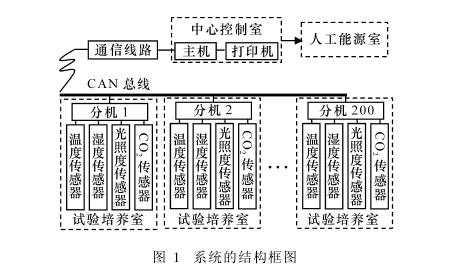
The system uses a PC (model 586/266 or higher) as the host computer, and an 80C592 single-chip microcomputer system and the temperature, humidity, light intensity, and CO2 content measurement circuit as extensions. As the core of the system, the host is placed in the control room of the system, and the extension is placed in each training room. In principle, an extension box is placed in a light box. One host can manage 1~200 extensions, and one extension can connect to detect 1~128 sensors such as temperature, humidity, light intensity and CO2 content. The host manages extensions (CAN nodes) placed in the culturing room within 10 km through the CAN serial bus; each extension collects and transmits information of state parameters through various sensors installed in the culturing room.
According to different types of plants in different growth periods and different growing seasons, the control room hosts set different ideal growth state parameters of the plants. At the same time, the host computer controls the artificial energy room to provide artificial energy to the training room by comparing the actual state parameters detected by the sensors installed in the extensions of the cultivating room with the set ideal state parameters, and through fuzzy operations and processing. This kind of communication method with CAN bus structure has the advantages of good real-time performance, low operating cost, convenient system setup and high reliability of work. The rational design of the host software is the key to the stable and reliable operation of the system. It directly affects the environmental state parameters required for plant growth.
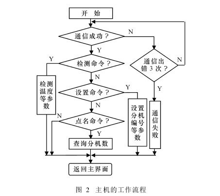
2 Host Software Design The host software design follows the modular design concept and adopts a structured program design program with good modularity, portability, and modificability. Host software modules mainly include: communication modules, data display modules, graphical display modules, historical data recording modules, data analysis and processing modules, decision-making and control modules. Among them, the graphical display of parameters such as temperature, humidity, illuminance, and CO2 content also has color prompting and warning functions. For example, when the temperature detection is graphically displayed, the red display indicates that the temperature is too high, the green indicates that the temperature is in the normal range, and the yellow indicates that the temperature is too low. When the system performs detection, according to the setting, the host first connects an extension or all extensions, and then transmits the measurement data collected by the extension to the host, stores it in the database, and performs analysis and processing. Thanks to the graphical display function, from the host display or printout, the operation of the training room can be obtained at a glance and system failure self-checking and other related functions can be achieved. The workflow of the host is shown in Figure 2.
2.1 Host Communication Software Module Design System host communication includes serial communication of host RS2232 and CAN bus communication between host and extension; CAN bus communication module includes communication software module such as name, detection, and setting.
2. 1. 1 host computer serial communication software design The host computer generally has two RS2232 serial communication mouths, this mouth finishes the serial data conversion and the serial data receive, the transmission duty, uses RS2232 communication standard, its structure and the use It's very simple. The MSCOMM control of the host system software VB provides event-driven and query methods to achieve serial communication. Among them: event-driven is a very effective method to deal with the serial port interaction; and the query method is to indirectly call API function through MSCOMM control, make full use of existing ActiveX control system to achieve rapid development is one of the advantages of VB; Both methods can realize serial port communication and data information transmission.
2.1. 2 CAN bus characteristics and working principle of artificial climate room CAN bus is a serial communication network that effectively supports distributed control or real-time control. It works in a half-duplex way, one node sends information, multiple Nodes receive information and can implement a fully distributed multi-machine system, improving the reliability of data transmission in the network. Its structure is shown in Figure 3.
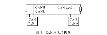
The information access of CAN bus adopts a kind of access method called broadcast type, the information can be sent to the free bus at any time by any node. The CAN bus interface of each node must receive all the information appearing on the bus. Therefore, each node is provided with a receiving register. The receiving register first receives the information, and then determines whether to read the data in the packet according to the identifier of the received information, that is, whether to use this information.
One of the greatest features of the CAN protocol is the abolition of traditional address coding, and instead of coding communication data blocks. The CAN bus is data-oriented instead of node-oriented. The advantage of this method is that it can theoretically limit the number of nodes in the network. Adding and reducing devices does not affect the system's work. Therefore, the system can arbitrarily change the number of extensions according to the different needs of users. The maximum length of the data sent and received by the CAN bus is 8 B, so there is no problem of taking up too much bus time, which can ensure the real-time communication. Communication speed up to 1Mb/s (communication distance 40m), communication distance up to 10km (transmission rate 5kb/s). The communication medium may be a coaxial cable or an optical fiber, and even a twisted pair may be used.
2.1.3 Named communication software module design The communication module such as point name, detection, and setting is basically the same in command format, because the command numbers executed by each are different, so different functions can be realized. The following detailed description of the communication module with the name command. The order name command is mainly used to query the number of extensions and the number of sensors attached to the extension, such as temperature, humidity, illuminance, and CO2 content. This command is generally executed when the system is powered on for the first time.
The number of CAN nodes in the artificial climate room is 1 to 200, so the host must know in advance the number of extensions and their addresses so that the host can manage them in a unified manner. The temperature, humidity, illuminance and CO2 content sensor of the substation is connected, and the 80C592 single-chip microcomputer used can connect the number of sensors distributed in the training room to 1 to 128. Therefore, the number of sensors managed by each extension in the system is also 1~. 128. Therefore, the system host must also know in advance the number of sensors and addresses of the extensions of the system, so as to complete the specific temperature, humidity, illumination, and carbon dioxide monitoring of specific areas in the training room.
The host name command format sent by the system host is: "0BBH" + CANADD + "0AAH" + cmnd + Bytes + Bytes + ad2rh + adrl + chkxor + chksum, where: "0BBH" is the start code of the host to send the command, that is, the command header; CANADD is the address of the CAN node in the system; “0AAH†is the main command, the extensions are among them, and the command start code for communication between the extension and each sensor; cmnd is the command number; Bytes, Bytl are the number of data bytes to be detected. , where Bytes is 8 bytes high, Bytes is low 8 bits, the total length of detected data = (Byteh* 256+Bytel) bytes; adrh, adr are the sensor type and sensor number of the detection object (each The object has its own fixed sensor model and sensor number, which is defined by the protocol; chkxor, chksum are XOR check and check respectively.
2. 2 VB and LabVIEW program nesting design Applying VB and LabVIEW to the host software development of the system can simultaneously utilize the technical advantages of VB and LabVIEW to form a flexible virtual instrument application system to realize graphical processing and monitoring of monitoring information. The effective control of the system.
2.2.1 Sharing of System Resources Use VB to complete the system's self-test, communication, historical data recording, data analysis and processing, decision-making and control software module design, using LabVIEW to complete the host system self-test, data display, graphical display Such as the design of software modules, the use of VB and LabVIEW together to complete the host self-test, data display, graphical display and other software modules design.
When the host collects the data transferred from the main concentrator from the serial port, it is managed by VB and the data is stored in the form of an Access database. The application of dynamic data ex2change (DDE) technology enables virtual instrument LabVIEW software platform to call the data in the database to display the parameter results. In this system, the use of powerful DDE series of functions to complete the data exchange and sharing work. Practice has proved that DDE technology is reliable and error-prone.
2. 2. 2 Embedding LabVIEW in VB
LabVIEW embedded in host software VB is implemented through OLE (object linking and embedding) technology, and OLE is the core technology of system host virtualization display. Using OLE technology, when developing the virtualization display function of the system host, the development program of the system virtual display part is centered on the Lab2VIEW platform (not VB as the center). With OLE, VB can embed LabVIEW software as an object into VB, and VB's handling of embedded LabVIEW is as quick and easy as handling its own objects. To implement OLE automation, first create a variable that references Lab2VIEW. This variable is called an Object Variable. Taking virtual temperature detection as an example, the source program is designed as follows:
Dim LVappAsLabVIEW.Application ———'Defining LabVIEW Application Variables Dim LVIAs LabVIEW.VirtualInstrument———'Defining Virtual Instrument Variables
Dim LVpathAs String————'Define the virtual instrument system path LVpath=APP. Path +":\LabVIEW\user. lib\Real-time temperature. vi"
SetLVapp=CreateObject("LabVIEW.Application") --'Start the Virtual Instrument Application
SetLVI=LVapp.GetVIReference(LVpath)————'The virtual instrument system to which the call path points
LVI.FPAutoCenter=True --- "When the virtual instrument program is run, the front panel of LabVIEW is in the center of the screen.
LVI.FPW inOpen=True --- 'Open and display the front panel when calling a virtual instrument program
LVI.Run (True) - - 'Run the virtual instrument program using the above code, you can embed LabVIEW in the VB program to achieve system graphics virtual panel function. After the virtual panel is generated, various controls in the panel can be operated to run or control the virtual instrument program. After the program finishes running, close the front panel of the virtual instrument to free up the computer's memory space.
3 Concluding remarks The CAN bus communication software of the artificial climate room intelligent test system host software adopts a full-range tracking and recording technology, which facilitates the understanding of the communication process by the staff and improves the system's ability to solve problems. VB and LabVIEW are applied to the artificial climate room intelligent test system, making full use of the advantages of VB's easy development and the graphical and modular programming advantages of the virtual instrument, so that the host software function is greatly enhanced. In addition, the system can be connected with other system software, and can achieve remote resource sharing and online information browsing and query.
Related Products: Temperature and Humidity Recorder Photosynthetically Active Radiation Recorder
Produce by Food Grade PP material, this PP spoon is a good solution for eating various dishes without getting hands involved . Its usability: Airline catering, food courts, hotels, parties, fast food and Ice cream outlets, coffee shops,picnic, outdoor events and all types of catering houses.


Plastic Spoon ,Disposable PP Cutlery,PP Disposable Spoon,Disposable Plastic Cutlery,Disposable Spoon,Reusable Plastic Spoons
BILLION PLASTIC MANUFACTURING CO.,LTD, JIANGMEN , https://www.jmflatbag.com