Plastic Fruit Box Making Machines
Meticulous division of labour, consecutive processes, professional of manufacture and high standard equipment ensure the high quality of the machine.
Factory introduced high precision maching tools, with the equipment of cutting machine tools, heattreating facilities, check out test sets and painting facilities, the processing ability for middle and large size machine, reach a high level in plastic industry while the quality if the machine is ensured at the same time.
All kinds of fruit and vegetables containers can be designed and produced by this machine.
All production line can be provided.
Vertification of many year's market application, optimal combination configuration, stable, reliable and durable system with the characteristics of high efficiency, energy saving, low voice and strong power.
The strengthening design of template is carried out through multiple times of optimization design of major components such as template, based on the analysis of finite element software, which both guarantee the lifetime of template and protected mould.
High rigid template adopts the structure with coexistence of installation screw hole and T-shaped groove.
The tie rod of each machine model has passed the test by professional testing organization, which means that, the deflection of tie rod is within reasonable scope while guaranteeing the operation of machine.
Plastic Fruit Box Making Machines,Smack-Box Making,Four Pillars Fruit Box Making Machine,Food Container Making Machine Ningbo Tongyong Plastic Machinery Manufacturering Co. Ltd. , https://www.tongyong-machinery.com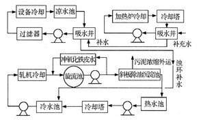
Fig. 1 Schematic diagram of the water circulation process in the rolling process
The water consumption of the rolling turbid water system is a variable, and the water treatment pump is a fixed pump. All of them rely on pressure relief valves to maintain the system stability and cause energy waste. Therefore, it is necessary to carry out frequency conversion of some motors of the slop ring pump in the rolling water treatment area, which saves water and saves energy.
The output power of high-pressure blower and water pump in the shale ring system and heating furnace system of Shaanxi Longmen Iron and Steel Group Co., Ltd. cannot be changed with the production load. Only by changing the opening degree of the damper, baffle, and valve, the load is adjusted. The efficiency is low, and there is a lot of energy wasted in throttling losses.
In order to improve the production efficiency of the bar water system and the rolling furnace system, reduce energy consumption and the overall reliability of the system, the high-pressure water pump of the bar water plant, the wire plant and the drive of the smoke exhaust fan and soot blower of the steel rolling furnace The system plans to use full digital AC high voltage variable frequency speed control system to implement control. High-voltage variable-frequency speed control system is directly connected in series between the high-voltage power supply and high-voltage motor frequency conversion speed control equipment, with its on-site transformation, easy installation and safety, good operating performance is quickly replacing other speed products, comprehensive access to metallurgy Energy-saving projects in the industry. The purpose of using high-voltage variable frequency speed control technology is to change the operating speed of the equipment to achieve the required wind pressure, air volume, and pump flow rate required to adjust the operating conditions at the site, which greatly improves the degree of automation of the system, which not only satisfies the production requirements, but also achieves Save energy, and reduce the economic losses caused by baffle and pipe wear caused by adjusting the baffles and valves, and the economic losses caused by frequent downtime inspections. At the same time, the maintenance volume is greatly reduced, which brings considerable benefits to the steel companies and responds to them. The country's call for energy conservation and consumption reduction.
Second, the application of frequency conversion speed control system This transformation mainly involves the following aspects: the system's main loop control program, the inverter system control program, on-site installation, and the inverter cooling program. The related system is described as follows:
2.1 The main loop control scheme of the system is based on the high-pressure water pump for the swirling pool water system of the bar mill, the net water pump and the bar-heating furnace air smoke fan, the coal smoke fan, the high-wire furnace soot fan, the air smoke fan, and the combustion air blower. Eight high-voltage inverters) using the main circuit are as follows: 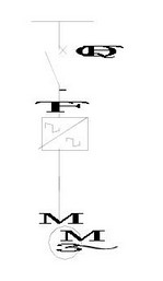
Figure 2 main circuit of frequency conversion speed regulation system
Note: QF1, M are the original equipment on site. Since the loads are all available, a one-to-one without-bypass control system is adopted, which reduces the investment cost while satisfying the reliability.
In Fig. 2, TF is a high-voltage frequency converter, which uses the LEED-Wah Fook brand perfect non-harmonic series high-voltage frequency converter. This series of inverters uses a series of low-voltage PWM inverter power units in series to achieve direct high-voltage output. The inverter has the characteristics of minimal harmonic pollution to the power grid, high input power factor, good output waveform quality, and no additional characteristics such as motor additional heating, torque ripple, noise, dv/dt and common-mode voltage caused by harmonics. With an output filter, an ordinary asynchronous motor can be used without replacing the motor in the field.
2.2 Inverter Control System This control system is mainly used to control remote and on-site automatic and manual control functions of 9 pumps in the Turbid Pump Room and 2 pumps in the rotary well, as well as relevant pipeline pressure, flow, and liquid level.
2.2.1 Control System Architecture 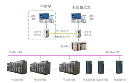
Figure 3 control system structure
2.2.2 Introduction to Control System This control system is mainly implemented by Schneider PLC to collect and control all real-time data such as pumps, pressure, flow, and liquid level, and monitors, controls and adjusts the inverter in real time. All control functions can be automated or manually controlled by remote or local methods. All the data collected by the PLC can be transmitted to the upper monitoring computer through the network in real time for data display, recording, management, printing, control and parameter adjustment functions.
The entire control system consists of two layers of network structure: the field control layer and the monitoring layer.
The on-site control layer is mainly used to connect PLC and frequency converter equipment, and is used to realize the collection of real-time operating status data of the inverter and the control and adjustment functions of the frequency converter.
The field control layer mainly connects PLC and frequency converter equipment in two ways: Profibus DP field bus and hard wiring method.
The monitoring layer is mainly connected to the monitoring computer of the PLC, muddy ring pump room and rolling line main control room through the Modbus TCP/IP industrial Ethernet network. It is used to realize the real-time collection, monitoring, recording, and management of all the equipment and instrument data on the site by the monitoring computer. Alarm; Real-time remote automatic control and adjustment of all equipment.
Due to the long distance between the cloud ring pump room and the main control room of the rolling line, a multi-mode optical fiber Ethernet switch device is used to connect all the monitoring computers.
2.2.3 Control mode In order to ensure the normal and reliable operation of the control system, the control system uses a variety of control modes to achieve real-time monitoring and control of the on-site water pump:
l Remote automatic: Real-time data acquisition and automatic control and adjustment of field devices through a host computer;
l Remote manual: real-time data acquisition and manual control and adjustment of field devices through the host computer;
l Inverter manual: Inverter provides the operation panel to realize the manual control and adjustment of the pump.
l Local manual: Through the manual control button of the inverter control cabinet can realize the manual control, adjustment and other functions of the water pump;
2.2.4 ProfibusDP control method ProfibusDP field bus: Real-time data exchange function between Profibus DP field bus and PLC. This method can transmit all relevant status information of the inverter to the PLC and the host monitoring computer in real time through the field bus, and real-time transmit the control and adjustment instructions issued by the host computer or PLC to the inverter to realize all the control of the local inverter. Features.
Leader Huafu inverter is compatible with ProfibusDP communication protocol, as long as the ProfibusDP communication cable is connected to the PLC communication module interface of the inverter, normal communication can be realized through the simple parameter setting in the inverter man-machine interface.
2.2.5 Hard-wired control method Hard-wired method: This method is a backup method of the Profibus DP field bus. If the Profibus DP bus fails, all monitoring and control functions of the field device can still be realized through hard wiring.
The interface of the hard-wired connection between the high-voltage frequency converter and the on-site DCS control system is as follows:
A. The digital output provided by the inverter is 8-channel:
(1) Indication of inverter standby status: indicates that the inverter is on standby and has starting conditions.
(2) Inverter operation status indication: Indicates that the inverter is running.
(3) Inverter control status indication: The node close indicates that the inverter control right is the field remote control; the node disconnect indicates that the inverter control right is the local inverter control.
(4) Inverter light fault indication: Indicates that the inverter generates an alarm signal.
(5) Inverter heavy fault indication: Indicates that the inverter has a heavy fault and immediately turns off the output to cut off the high voltage.
(6) Emergency breaking of high voltage: When the frequency inverter has a heavy fault, the high voltage switch of the incoming line is automatically broken.
(7) High pressure closing allow: The frequency converter passes the self-test or the system is in the power frequency state, allowing high pressure.
(8) The motor is bypassed at the power frequency: the motor is in the power frequency bypass state.
All the above digital quantities use passive contact output, defined as valid when the contact is closed. Unless otherwise specified, the contact capacity is AC220V, 3A/DC24V, 1A.
B, DCS provides 4 channels for the inverter:
(1) Start command: dry contact, valid when 3 seconds pulse is closed, the frequency converter starts running.
(2) Stop command: dry contact, valid when 3 seconds pulse is closed, inverter stops normally.
(3) High pressure ready: dry contact, when the high voltage switch is in breaking, the auxiliary node is open, the inverter input is live, and the inverter can start.
(4) Open signal of high-voltage switch: when the high-voltage switch is in disconnection, the auxiliary node is closed;
C. Analog quantity 2-way provided by frequency converter:
(1) Inverter output speed (2) Inverter motor current The inverter provides two 4 ~ 20mADC current source outputs (inverter power supply), with a load capacity of 250Ω.
D, DCS provides analog frequency 1 way to the inverter:
(1) Inverter speed setpoint provides one 4- to 20mADC 2-wire current source output on site. The load capacity must be greater than 250Ω, and 4~20mADC corresponds to the low speed limit, which must be linear.
2.3 Cabinet installation (1) Inverter equipment installation, should consider the need for ventilation and heat dissipation and operating space, the distance from the back of the whole device to the wall shall not be less than 1000mm, the distance between the top of the device and the roof space shall not be less than 500mm, the distance from the front of the device to the wall shall not be less than 2000mm, the distance from the side of the device to the wall must be not less than 1000mm, which is convenient for installation, commissioning and maintenance personnel.
(2) All cabinets should be securely mounted on the base and be reliably connected to the factory floor. Ground terminal PE should also be connected to the factory floor. The cabinets should be connected to each other as a whole.
(3) The high-voltage frequency converter adopts a one-to-one system,
No bypass cabinet, the same dimensions, as shown below: 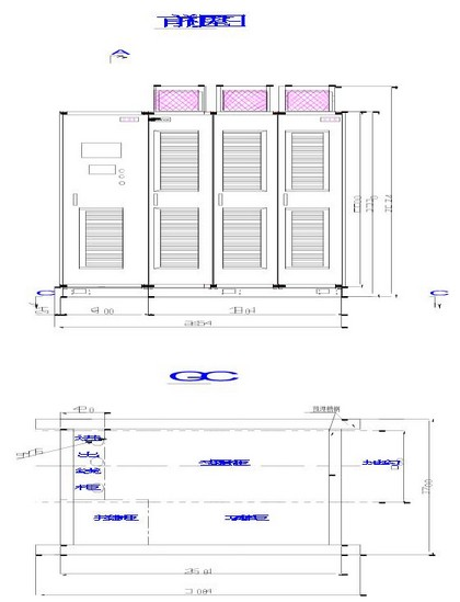
Figure 4 Inverter installation dimensions
2.4 Heat Dissipation Schemes 2.4.1 Comparison of Heat Dissipation Schemes Introduction High-voltage inverters are large-scale electronic devices. Their energy consumption is high during the operation. The energy consumed by the inverter is converted into heat, and the heat is transferred to the cooling fan through the inverter. In addition to the inverter body, since the absolute value of this part of heat is relatively large, it generally reaches several tens of kW. If no measures are taken to properly handle it, the operating environment temperature of the inverter may be too high, which will affect the normal operation of the inverter.
At present, there are three common solutions:
1) Open air duct installation The air hood collects the hot air discharged from the inverter and directly discharges the hot air from the inverter outside the installation environment. The advantage is that the construction is convenient and the construction cost is low; the disadvantages of the operating stability depend on the local environment;
2) Air-conditioned closed cooling Air-conditioning is installed in the room where the inverter is installed, and the air temperature is used to reduce the ambient temperature. The advantage is that the construction is convenient, the maintenance is low, and the operating environment of the inverter is good; the disadvantage is that the early-stage cost input is high, long-term High operating energy consumption;
3) Air-cooled air-cooled installation of air-cooled air-cooled coolers, similar to air-conditioning, has the advantage of being able to use existing on-site resources (cooling water in the field), and the equipment operating costs are equivalent to 1/3-1 of the same heat-exchange power air-conditioning. /4, The low operation and maintenance costs make the inverter's operating environment good; the disadvantages are high initial cost investment and relatively complicated installation and debugging.
Comprehensive comparison of the above three options, it should be said that each has its advantages and disadvantages, the user will generally according to their own characteristics and requirements choose the most suitable for their own conditions to implement the program.
2.4.2 Efficient heat dissipation scheme that meets the actual conditions of the site is calculated according to 96% of the operating efficiency of the high-voltage frequency converter: The maximum heat dissipation power of the frequency converter is: Frequency conversion rated power × 4%. According to the actual situation on the spot, integrating the investment in cooling system and operating costs, the following cooling schemes are proposed:
1) Air duct open cooling (1) Cooling process The cold air enters the inverter through the inverter room inlet filter. After the body is cooled, the hot air is discharged from the inverter air outlet.
(2) Installation method The open air duct cooling construction is relatively simple. The hot air of the inverter is collected through the wind hood. Only the air duct needs to be produced at the scene, and the hot air is discharged to the outside through the air duct; two openings are opened on the wall of the inverter room. , install the filter, as the inlet hole. As shown below: 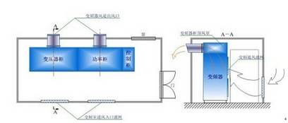
Figure 5 Inverter air duct cooling installation
According to the actual situation of the actual situation of the site, the inverters are arranged as follows:
Two 280kW/10kV net-ring pumps are planned to adopt a set of high-voltage inverters. The inverter room is built in the open space behind the net-ring pump. The houses are as follows: 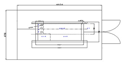
Figure 6 Single-frequency inverter in a room
Three high-pressure water pump motors (315 kV/10 kV) in the spinning mill system of the bar plant are required to be frequency-converted to reform the two pumps. A high-voltage frequency converter room is built next to the surface of the swirl pool. The drawings are as above.
Bar plant spinning pool net water system another motor; rod line furnace soot fan, air smoke fan; high-wire furnace fan, soot draught fan, air smoke draught fan, a total of six devices are arranged in one Between the new (built-in frequency converter room base height is about 60mm indoor cable trench), frequency converter room as shown below:
Figure 6 Inverter indoor layout diagram III. Application effect analysis Due to the high frequency of load regulation during field operation, the following data are calculated based on the empirical values ​​of the same conditions and the data collected on site.
3.1 Power consumption calculation under power frequency Pd: Motor power; Cd: Annual power consumption value; U: Motor input voltage; I: Motor input current; cosφ: Power factor; T: Annual operating time; δ: Single load Percentage of running time Motor power consumption calculation formula: Pd=×U×I×cosφ...1
Cumulative annual power consumption formula: Cd=T×∑(Pd×δ)...2
According to calculation formula 12, the power consumption of a single load under the power frequency condition can be obtained as follows: 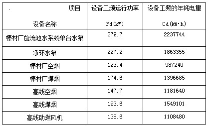
Pd′: motor shaft power; P′: fan (pump) shaft power; motor efficiency;
: Actual efficiency of frequency converter; Q: Outlet flow of fan (pump); H: Pressure difference between outlet and inlet of fan (pump), λ: Characteristic coefficient of pipe network.
By shaft power: P′=...6,
Substituting the rated value of the fan (pump), the pipe network characteristic coefficient λ is obtained.
The shaft power can be obtained by substituting the pressure, flow value of the fan (pump) under different loads into the above formula.
The relationship between motor efficiency and motor load ratio β is shown in Figure 1 below.
The relationship between inverter efficiency and system load rate β is shown in Figure 2 below. 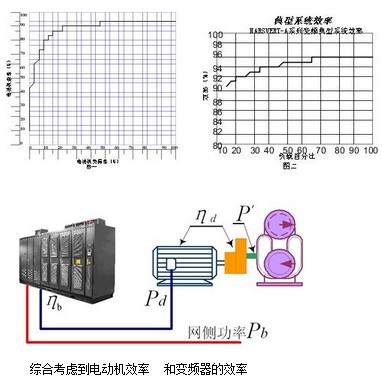
Cumulative annual power consumption formula: Cb=T×∑(Pb×δ)...8
According to the calculation formula, the power consumption of each load of a single station in the case of frequency conversion can be obtained as follows: 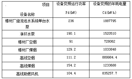
Saving rate = (ΔC/Cd) × 100% ... 10
After the frequency conversion reformation, according to formula 910, the annual power saving compared with the power frequency after the single load is up-converted is calculated as follows:
Note: 1) The above calculations are all theoretical calculations and there is a deviation of ±3%;
2) The annual running time of the equipment is calculated according to 8000 hours.
Fourth, the application of other high-voltage variable frequency speed control system benefits 4.1 Reduce the amount of maintenance After the use of variable frequency speed control, no matter what kind of process conditions, at any time by adjusting the speed to make the system work near the rated state, under normal circumstances, the frequency control system The application is mainly to reduce the speed of the motor. Due to slow start-up and reduced speed, the life of many components is correspondingly prolonged; at the same time, the impact on the pipeline is greatly reduced, the inspection period of the pipeline is effectively prolonged, maintenance and repair expenses are reduced, and large maintenance costs are saved.
4.2 Work Intensity Reduction Because the speed control system implements computer interlock control between the operating equipment and the standby equipment, the unit achieves automatic operation and corresponding protection and fault alarms. The operation is changed from manual to monitoring, and the unmanned operation of the production is completely realized. The labor intensity is greatly reduced, the production efficiency is improved, and a reliable guarantee is provided for the optimization of the operation. 4.3 Reduction of the impact on the power grid After the frequency conversion adjustment is adopted, the system achieves soft start, the motor starting current is much smaller than the rated current, and the start-up time is prolonged accordingly. There is no big impact on the power grid, which reduces the mechanical damage to the motor caused by the starting mechanical torque and effectively extends the service life of the motor.
The Application of Leader Huakang High-voltage Frequency Converter in Turbine Ring System and Heating Furnace System of Longgang Group Rolling Mill
First, the rolling water system and heating furnace Introduction The rolling mill production water use recirculating water system, circulating water system is divided into three parts, namely heating furnace, net ring, turbid water system. From the process point of view, the entire circulating water system of the rolling process can be divided into two parts: the net ring system and the muddy ring system according to the water quality after the water is used. The cooling method of the heating furnace and equipment is indirect cooling. After the water is used, only the water temperature rises, and the water quality is not polluted, which is a net ring system. The cooling method of the rolling mill is direct cooling, and the water after use not only increases the water temperature, but also the water quality. It has been contaminated by iron oxide skin and oil. It belongs to the turbid ring system. The flushing of the iron oxide skin is a small circulatory system in the system. The water only requires water pressure. 3.2 Annual power consumption calculation under frequency conversion status For common fan and pump load, the calculation under frequency conversion status is as follows: Considering the efficiency of the motor and the efficiency of the inverter, the power consumption of the network side: ...7 3.3 Energy Saving Calculation Annual Electricity Consumption: ΔC=Cd-Cb...9